4L60E Transmission Rebuild Page 23 of 29
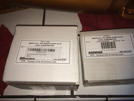
Figure 89. The servo assembly is next. The Sonnax Super Hold 2nd and 4th servos will be used for this.
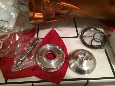
Figure 90. These are the components for the 2nd Super Hold Servo. The original cushion spring, retaining ring, pin spring washer, and e-clip will be re-used.
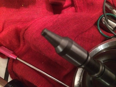
Figure 91. This is the new shaft tip for the servo. It will need to be ground down and fit to the transmission, the process involves assembling the servos without the o-rings, setting up a dial indictor on the outside of the servo, and checking for travel distance. The specification is for travel to be between .075 and .125. The pin will need to be ground down quite a bit.
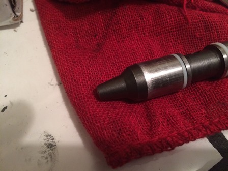
Figure 92. This is the old pin, you can see how much shorter the pin is than the new one.
| Pages: 1, 2, 3, 4, 5, 6, 7, 8, 9, 10, 11, 12, 13, 14, 15, 16, 17, 18, 19, 20, 21, 22, 23, 24, 25, 26, 27, 28, 29 |
| <--Previous | 4L60E Rebuild Home | Next--> |
| Contact: Copperhead | As an Amazon Associate I earn from qualifying purchases | © 2019 |