4L60E Transmission Rebuild Page 24 of 29
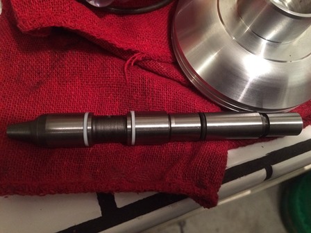
Figure 93. This is the new pin after fitting. The servo assembly will be taken apart and put back together several times, while grinding the pin down to fit. You only want to grind a small amount at a time, as you can not add material back to the pin. Go slowly and measure carefully.
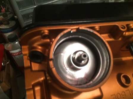
Figure 94. Assembling the servo for the final time. Here is the 2nd servo assembly in its bore.
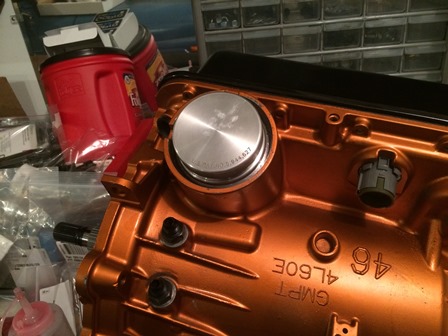
Figure 95. The 4th super hold servo in the bore and done. This completes the main part of the transmission rebuild.
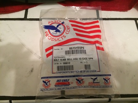
Figure 96. These are the new bellhousing bolts. There was quite a surprise when time came to install them. Unlike the stock GM bolts which have a torx+ 50 head, these have a regular torx 50 head. The Torx Plus bit will not fit in them. A new tool had to be purchased to put them in.
| Pages: 1, 2, 3, 4, 5, 6, 7, 8, 9, 10, 11, 12, 13, 14, 15, 16, 17, 18, 19, 20, 21, 22, 23, 24, 25, 26, 27, 28, 29 |
| <--Previous | 4L60E Rebuild Home | Next--> |
| Contact: Copperhead | As an Amazon Associate I earn from qualifying purchases | © 2019 |